Description
Generally, it is necessary to select one or several objects before an action can be carried out. To this end, there is the Select, Move, Scale tool. Furthermore, this tool can also move and scale objects.
If the Select, Move, Scale tool is merged with the Edit tool (cf. Options dialog Tools General), this tool lets you move corners, add new corners or remove existing ones as well the edge lengths of parametric objects can get adjusted by this tool too.
How do I activate it?
The Select, Move, Scale tool can be activated with the command Select, Move, Scale from the menu Tools or by clicking on the ![]() icon in the Toolbox flyout. When the tool is active, the mouse takes the shape of an arrow or a symbol of an action, which potentially could be executed.
icon in the Toolbox flyout. When the tool is active, the mouse takes the shape of an arrow or a symbol of an action, which potentially could be executed.
How do I use it?
Mouse
The use of this tool is similar to the mouse control in Windows Explorer. To select an object, just click on it. The outlines of the selected object are highlighted with a particular line (cf. the corresponding option in the Options dialog window category Application>User Interface). This means that the object is active.
To mark several objects, hold down the Shift key then click on the next object. It is also possible to select several objects at the same time by clicking on a point (which does not belong to an object) or by holding down the Alt key and then drawing a rectangle. All objects, which are entirely in this designated area, will be marked. In the expanded selection mode (cf. Options dialog window, category Application>Tools>General), whereby if the start point is to the right of the endpoint, all objects will be marked that are only partly contained within the rectangle.
If you would like to mark all the objects, which are present on a report page, you can do this with the menu command Edit.Select All out of the menu or with the keyboard combination Ctrl+A
To move objects, you must first mark them. Now you can click on one of the selected objects and move it to a desired position with the mouse (the mouse button must be kept down while moving it). With the Shift and Ctrl keys, you can influence the behavior of the object while you move it. If you hold down Ctrl while moving the object, then a copy of the object will be moved, the original object will remain untouched. If you hold down the Shift key, then the object can only be moved vertically and horizontally. It is also possible to combine both options at once.
Objects (or copied objects) will snap to a reference point when they are being moved if the snap option is set. The position of the reference point corresponds to that of the corner point, which is closest to the mouse click. If you want the upper left corner to be the snap reference for that object, then you must click near the upper left corner of the object.
The reference point is marked with a little circle when the object is being moved, and after moving it, it becomes a filled circle ![]() .
.
To scale an object, you must also select it first. Unlike moving an object, you must click on one of the highlighted points and then move it (you should keep the mouse button held down). You can then see how the object gets bigger or smaller. If you hold down the Shift key while scaling, then the scaling is done proportionally: that is the vertical increase (or decrease) matches that of the horizontal.
Corners, Edge length
If the Select, Move, Scale tool is merged with the Edit tool (cf. Options dialog Tools General), you can modify also corner points and edge lengths, otherwise this has to be done using the Edit tool.
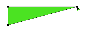
Click on the corner point that you would like to move. The point, which is now highlighted in black (see figure 1), can be moved by clicking on it and moving the point.
To delete a corner point, choose the command Remove Vertex from the context menu as you right click on the particular vertex.
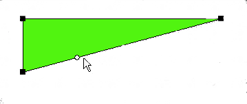
To add a new corner point, click on the spot on the line where you want to insert the vertex. A small circle now marks the spot (see figure 2). Now choose the command Split Edge from the context menu (right click) in order to add the new corner point.


Keyboard
You can also numerically adjust the position, the size and the scale of one or more than one object.
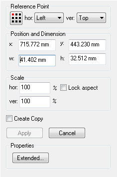
Make sure that the object is selected and the tool properties are visible (see figure 3). If this is not the case, you activate the Toolbox flyout and the Select, Move, Scale tool. You can now activate the properties with the Tab key or by clicking on a field. You can activate the individual fields by repeatedly hitting the Tab key or by using the Tab key while the Shift key is held down.
The x: and y: fields are relevant for the position of the object. These fields are the coordinates of the reference point. The red point on the reference point control ![]() indicates, which point on the object (corner, midpoint, or object center) is to take the coordinates. You can change the reference point (after activating it with Tab) with the arrow keys or with the mouse. You can finish the input by either clicking on the Apply button or by activating it with the Tab key and then hitting Return.
indicates, which point on the object (corner, midpoint, or object center) is to take the coordinates. You can change the reference point (after activating it with Tab) with the arrow keys or with the mouse. You can finish the input by either clicking on the Apply button or by activating it with the Tab key and then hitting Return.
You can also move an object a little at a time vertically and horizontally with the arrow keys.
You can change the size of the selected object by entering the width ![]() and the height
and the height ![]() of the bounding rectangle. You can finish the input by either clicking on the Apply button or by activating it with the Tab key and then hitting Return.
of the bounding rectangle. You can finish the input by either clicking on the Apply button or by activating it with the Tab key and then hitting Return.
You can change the scale of the selected object, by entering a value into the field marked with a %. Within the upper % field, you change the width by the corresponding magnitude, within the lower % field, you change the height. If the scaling should be done proportionally, you can activate the option Lock aspect. You can then finish the input by either clicking on the Apply button or by activating it with the Tab key and then hitting Return.
If the option Create Copy is activated, a duplicate will automatically be created.
All coordinates correspond to the current coordinate system. The origin of the coordinate system can easily be adjusted.

Figure 3: Select, Move, Scale tool properties