Description
The U-Value tool kind Parallel Layers allows you to prompt the U-value for any given construction section and creates a label of that value in the diagram.
How do I activate it?
The U-Value tool can be activated with the command U-Value in the menu Results or by clicking on the ![]() icon in the Toolbox flyout. Then select Parallel Layers as kind in the tool properties (cf. figure 2). When the tool is active, the mouse becomes a
icon in the Toolbox flyout. Then select Parallel Layers as kind in the tool properties (cf. figure 2). When the tool is active, the mouse becomes a ![]() in the area of the construction.
in the area of the construction.
How do I use it?
With a first click the point where the cross section line should be is defined. The direction of the cross section line should be perpendicular to the nearest edge. If the mouse button is held down a dashed preview appears as well as the label, which can be placed accordingly. You can define the ultimate position of the label by releasing the mouse button (see figure 1).
If you would like to interrupt the entry, then hit the ESC key.
With the Select, Move, Scale tool or Edit tool respectively, you can change the position of the label along with the position of the cross section line for which the U-value should be calculated.
The style of the label (e.g. the number of post decimal place holders) along with the graphical properties of the cross section line can be adjusted with the corresponding styles in the Styles flyout.
In the Properties flyout (cf. figure 2) you can adjust the calculation rule in addition to the style: You can define transition resistances or coefficients other than those that occur at the cutting plane and fix the angle of the cutting plane.
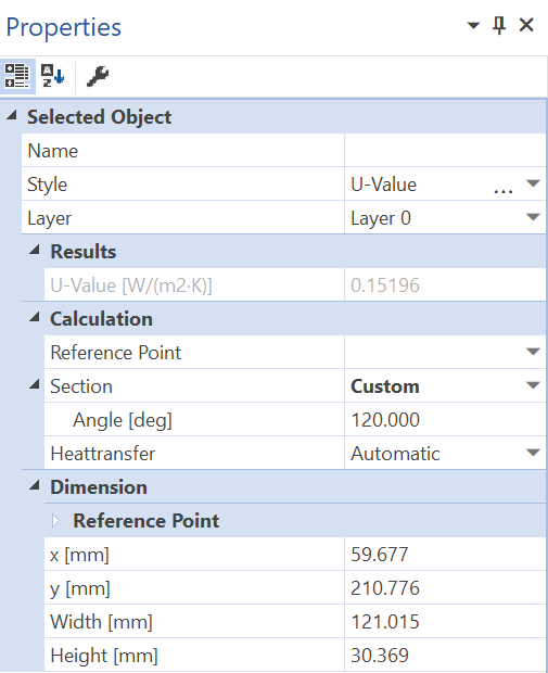
Figure 2: Properties flyout of an U-value object
Defining Styles
The presentation of an U-value object can be defined in the Style list in the U-Value tool properties (see figure 3). The list shows all styles for U-value objects that have previously been determined in the Styles flyout.
A new U-value object will always be created with the styles currently marked in the Style drop down list. You can either change the selection of the styles in the Styles flyout or in the Style drop down list in the U-Value tool properties.
The styles can also be adjusted afterwards by using the Assign Properties tool or by using the Drag&Drop function (see lesson 1).
Figure 3: U-Value tool properties
 Significant Results
To receive significant results the following conditions have to be fulfilled:
•U-values should only be calculated from examples with parallel layers (e.g. like in figure 1).
Physical Explanation
The U-value of a construction cross section of a layered component is calculated according to the following formula:
where:
U: U-Value [W/m2K]
hi: interior heat transfer coefficient [W/m2K]
dj: thickness of layer j [m]
λj: thermal conductivity of the layer j [W/mK]
he: exterior heat transfer coefficient [W/m2K]
Comments
•The measurement dj is based on the cross section line.
•A requirement is that all the layer boundaries are parallel and perpendicular to the cross section line as in figure 4. The calculation of the U-value, therefore, only makes sense in the boundary areas and in the middle of this construction.
 Limitations
•This tool can only be used on the report page and only if result objects of a previously calculated model are present.