Description
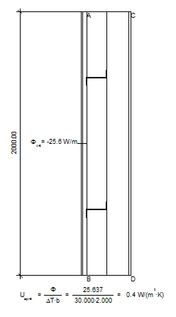
The U-Value tool Equivalent U-Value allows you to calculate and display equivalent U-values. The equivalent U-value takes periodic thermal bridge occurrences into account (e.g. the joist in figure 2).
How do I activate it?
The U-Value tool can be activated with the command U-Value in the menu Results or by clicking on the ![]() icon in the Toolbox flyout. Then select Equivalent U-Value as kind in the tool properties (cf. figure 1). When the tool is active, the mouse becomes a
icon in the Toolbox flyout. Then select Equivalent U-Value as kind in the tool properties (cf. figure 1). When the tool is active, the mouse becomes a ![]() .
.
How do I use it?
To calculate the equivalent U-value over a surface edge two clicks are required:
With the two clicks (in the example below for the points A and B) you set the cross section lines and thus determine the surface tension, over which the equivalent U-value is calculated. After the second click, the equivalent U-value is calculated.
If the Shift key is held down during the definition of the surface line, the first click automatically sets start and end points at the adjacent adiabatic edges (e.g., part cuts) and calculates the equivalent U value.
In the Properties flyout (see Figure 4) you can adjust the calculation rule in addition to the style: you can specify a different reference length and a different temperature difference than the automatically determined ones.
Defining Styles
The presentation of an equivalent U-value object can be defined in the Style list in the Equivalent U-Value tool properties (see figure 1). The list shows all styles for equivalent U-value objects that have previously been determined in the Styles flyout.
A new equivalent U-value object will always be created with the styles currently marked in the Style drop down list. You can either change the selection of the styles in the Styles flyout or in the Style drop down list in the Equivalent U-Value tool properties.
The styles can also be adjusted afterwards by using the Assign Properties tool or by using the Drag&Drop function (see lesson 1).
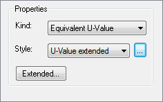
Figure 1: Equivalent U-Value tool properties
 Accurate Results
To receive accurate results, the following conditions must be fulfilled:
•equivalent U-values should only be calculated for constructions where thermal bridges appear periodically (cf. figure 2).
•the cross section line should be defined within sections, through which no heat flow flows (e.g. symmetrical axes or on edges where there the boundary condition: heat flux q=0.0 W/m2K is set).
•If you choose an exterior reference system, start and end points should lie on the exterior boundary of the construction. If you choose an interior reference system, start and end points should lie on the interior boundary of the construction. Make note of the order of the inputs: also here endpoint inputs are entered counterclockwise.
•Also consider the Comments section in the chapter Physical Explanation .
If you would like to interrupt the input before defining the 3rd point, you can use context menu command (right click) Cancel or you can hit the ESC key.
With the Select, Move, Scale toolor Edit tool respectively, you can change the position of the label as well as the position of the section.
The type of label (e.g. number of post-decimal place holders, whether the heat flow should be calculated through the section surface) as well as the graphical properties of the cross section line can be adjusted with the corresponding styles in the Styles flyout. You can either enter the values manually, copy the values from another result object (![]() ) or link the calculation to other result objects (
) or link the calculation to other result objects (![]() ).
).
Physical Explanation
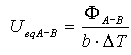
The equivalent U-value (previously equivalent K-value) is calculated as follows:
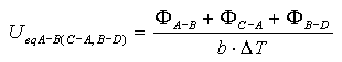
and calculated as follows if the heat flux through the section should be taken into account (cf. figure 4, Properties flyout)
where:
Ueq: equivalent U-value [W/m2K]
ΦA-B: heat flow from A to B (counterclockwise) [W/m]
ΦC-A: heat flow from C to A (counterclockwise) [W/m]
ΦB-D: heat flow from B to D (counterclockwise) [W/m]
b: length of the projection of the distance line AB on the perpendicular to the section line AC [m]
ΔT: temperature difference TA-TC of the boundary condition temperatures TA und TC by the points A and C [K]
Comments
•In general, the equivalent U-values are dependent on the side of a construction (interior or exterior) for which the value is being calculated. The following relations are valid:
Ueq A-B, exterior= Ueq A-B (C-A,B-D), interior and Ueq A-B, interior = Ueq A-B (C-A,B-D), exterior
•In case the heat flow through the section surface exceeds a critical, relatively high value, then an appropriate warning will be shown. You can adjust these borders in the Properties flyout (cf. figure 4)
•The heat flows will be calculated counterclockwise from start to endpoint.
•To calculate the heat flow, all reference points will automatically be shown at the nearest mesh point on the surface.
•The sign of the heat flow is taken into account: heat flows into the system are positive; heat flows out of the system are negative.
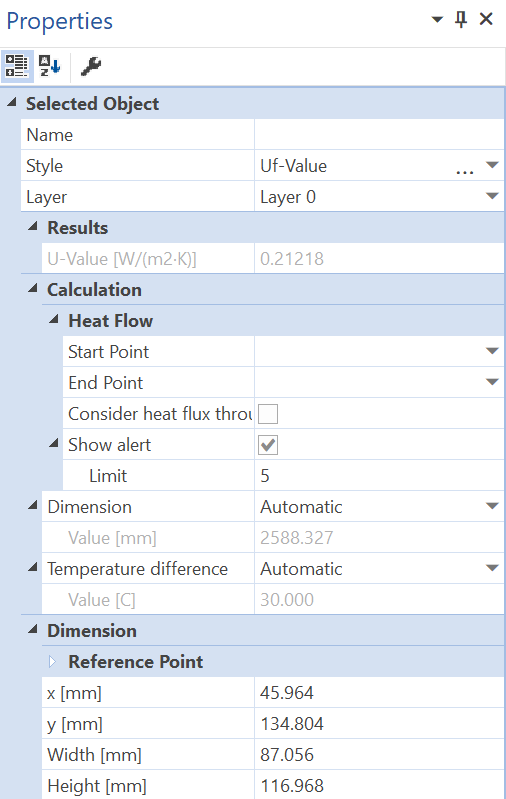
Figure 4: Properties flyout of a equivalent U-value object
 Limitations
•This tool can only be used on the report page and only if result objects of a previously calculated model are present.
•The temperature differences must have the same values for both sections.
•Only 2 boundary condition temperatures can be present in the model.
•Neither interior borders nor heat sources can be present.