Description
The U-value tool frame Ufr- and Ueg-value enables the calculation and display of frame Ufr- and Ueg-values according to ISO 15099.
How do I activate it?
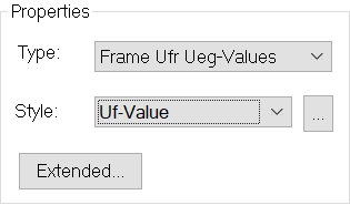
The U-Value tool can be activated with the command U-Value in the menu Results or by clicking on the ![]() icon in the Toolbox flyout. Then select the type of frame Ufr- Ueg-values in the tool properties (cf. figure 2).
icon in the Toolbox flyout. Then select the type of frame Ufr- Ueg-values in the tool properties (cf. figure 2).
How do I use it?
To calculate the Ufr value over a surface train, you need two clicks:
With the two clicks (in the example below for the points m1 and m2) you determine the surface and the dimension, over which the heat flow is calculated. Together with the temperature difference the Ufr -value is calculated. The Ueg-value(s) are automatically calculated using the dimension of 63.5 mm specified in the ISO 15099 standard.
The dimension for the Ufr-value calculation, the slope of dimensioning the Ueg-value and the temperature difference can be adjusted later in the Properties flyout (see figure 1).
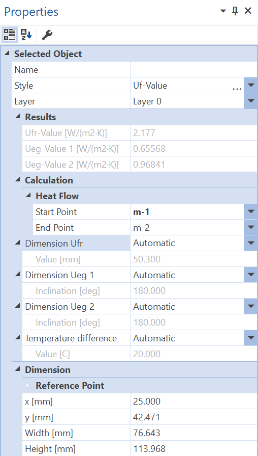
Figure 1: Properties flyout for an Ufr-value and Ueg-value object
The calculation of the Ufr- and Ueg-value is explained in detail in lesson 5.
You can change the dimensions manually by using the Select, Move, Scale tool or the Edit tool to move the position of the starting points of the dimension lines accordingly. You can use the same tools to change the text positions of the help objects and the distance of the dimension lines.
Defining Styles
The presentation of an Ufr-value object can be selected in the Style list in the tool properties (cf. figure 2). The list shows all the Ufr- and Ueg-value styles previously defined in the Styles flyout.
A new Ufr-value object is always created with the styles currently marked in the Style drop down list. You can either change the selection of the styles in the Styles flyout or select the according style in the Style drop down list of the tool properties.
The styles can also be adjusted afterwards by using the Assign Properties tool or by using the Drag&Drop function (cf. lesson 1).
Physical Explanations
The frame Ufr-and Ueg-value is calculated according to ISO 15099 as follows:
Figure 3: Calculation of Uf-values
with:
Φ: Heat flow through the corresponding surface [W/m]
ΔT: Temperature difference [K]
b: Width of the frame [m]
 Limitations
Ufr and Ueg values can only be calculated for constructions that are recognized as window frames according to ISO 15099:
•There are exactly 2 air temperatures in the boundary conditions.
•There are exactly 2 adiabatic boundary conditions ("symmetry / component section") on each of the two component sections.
•The glazing units and panels are long enough to calculate the Ueg value