Description
With the U-Value tool Joint U-Value you can calculate and display Joint U-Values according to EN ISO 12631.
How do I activate it?
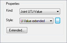
The U-Value tool can be activated with the command U-Value of the menu Results or by clicking on the ![]() icon in the Toolbox flyout. Then select Joint UTJ-Value as kind in the tool properties (cf. figure 4).
icon in the Toolbox flyout. Then select Joint UTJ-Value as kind in the tool properties (cf. figure 4).
How do I use it?
Click with the tool on the result object for which the Joint U-value should be calculated. Unlike to the Uf-value the given construction including glazing and spacer is analysed.
Then the frame materials which define the frame measurements have to be determined in the opening dialog window. Consider that these materials should only be used exclusively in the frame. If necessary, you have to create duplicates of materials (e.g. aluminium frame and aluminium panel) and you have to assign them to the according domains on the model page.
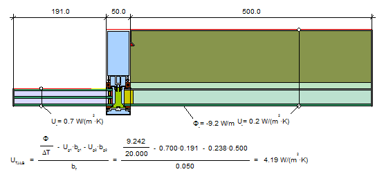
Figure 1: Example of a Joint U-Value object
You have to define the frame materials which determine the frame measurements in the opening dialog window. Alternatively the kind and orientation of the frame can be set in the dialog window.
The type to determine the frame width (Automatic, 2 Constructions or 3 Constructions) can be customized later in the Properties flyout (cf. figure 2). If the frame width is determined automatically based on the selected frame materials, the method to calculate the frame width (Max of projections, Cold side projection, Warm side projection), as well as the frame materials themselves, can be customized later in the Properties flyout (cf. figure 2) too.
For the non-automatic calculation based on the frame materials, you can adjust the frame width, the glass package lengths and U-values if necessary. You can either enter the values manually, copy the values from another result object (![]() ), or link the calculation to other result objects (
), or link the calculation to other result objects (![]() ).
).
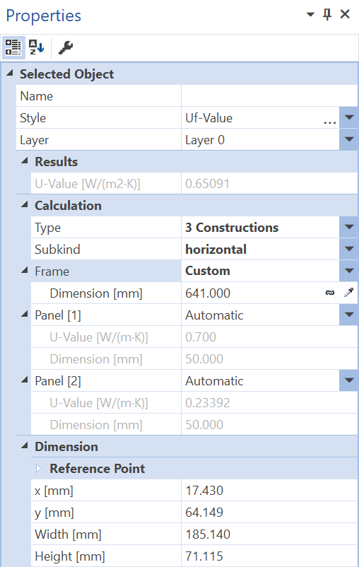
Figure 2: Properties flyout for the joint U-value object
The definition of a joint U-value is explained in detail in lesson 5.
In special cases, if the frame width can't be exactly defined using the frame materials (e.g. "Z-Profiles"), you can also adapt the dimension manually by moving the position of the start points of the dimension objects using the Select, Move, Scale tool or the Edit tool respectively. You can also change the text positions of the help objects, of the U-values of the base construction and the dimension lines with the same tool.
Also it's possible for rare cases to define all needed key values (dimensions, U-values of the glazing units) for the Joint U-value calculation manually in the Properties flyout.
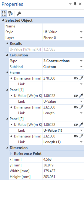
Figure 3: Properties flyout for an UTJ-value object with custom calculation
Defining Styles
The presentation of a joint U-Value object can be selected in the Style list in the tool properties (cf. figure 4). The list shows all styles for joint U-value objects that have previously been determined in the Styles flyout.
A new joint U-value object is always created with the styles currently marked in the Style drop down list. You can either change the selection of the styles in the Styles flyout or select the according style in the Style drop down list of the tool properties.
The styles can also be adjusted afterwards by using the Assign Properties tool or by using the Drag&Drop function (cf. lesson 1).
Physical Explanations
The joint U-value is calculated according to EN ISO 12631 as follows:
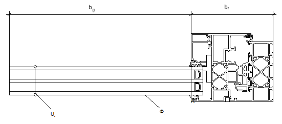
Figure 5: Calculation of a joint U-value
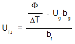
with:
Φ: Total heat flow in to or out of the model [W/m]
ΔT: Temperature difference [K]
Ug: U-Value of the panel or glazing [W/m2K]
bg: Width of the glazing or the panel [m]
bf: Width of the frame [m]
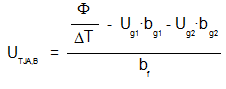
If the calculated construction is a mullion or a transom, than 2 glazing or panels are used, the formula is as follows:
 Limitations
Joint U-values can only be calculated for constructions, which are recognized as window frames according to EN ISO 12631:
•Materials which defines the frame dimension can occur exclusively in the frame (if necessary, you have to create duplicates of materials).
•There are exactly 2 boundary condition temperatures.
•There are exactly 2 adiabatic boundary conditions ("Symmetry/Model Section" ) each one on both model sections.
•Either it's a horizontal or a vertical window